.avif)
.png)
Tired of Mass Timber Challenges Derailing Your Projects? Learn How to De-Risk & Deliver Them.
Lead mass timber projects with confidence — and leave delays, redesigns, and budget blowups behind.
✅ Solve early-stage design, sourcing, insurance, permitting, code & cost hurdles before they derail your project.
✅ Find technical answers on design, detailing, procurement, embodied carbon ROI, hybrid systems & more.
✅ Build relationships with developers, GCs, architects, and engineers shaping mass timber’s future.
Get your ticket— and get the insights, skills, and network to deliver mass timber projects successfully.
Latest episodes
Stop Waiting for Better Building Products w/ Zenon Radewych of WZMH Architects
The building industry has a strange relationship with its own materials. Most of the people designing, engineering, and building things treat the products and materials as a fixed list of options. If the available products don't quite do what the project needs, the project bends to fit the products.
But not all. Some people have stopped accepting that. Instead, they’ve leaned into the “what if we had this…” or “what if we made that?” They've built the inventor’s mindset into their companies, literally and figuratively.
Zenon Radewych is one of them. He's a principal at WZMH Architects, a 65-year-old firm based in Toronto, and the person behind @sparkbird, their R&D lab where they don’t let what’s currently available limit their options. And now, they’re looking at mass timber.
This article is just one part of the newsletter where we cover who and what’s shaping the mass timber industry.
👉 Stay ahead of the mass timber industry & grow your network. Join Our Newsletter
A Lab Isn't a Department. It's a Permission Slip.
When most people in this industry hear “R&D lab,” they picture a big space with a big budget. A formal program. A roadmap. Milestones. Maybe a Ph.D. or two.
sparkbird isn't that. It's a corner of the WZMH office where people work on things that interest them, often without a deadline, often without a guarantee that anything will come of it. Ideas come from client meetings, from frustration with how a project went, from a side problem that showed up while solving something else. Some of those ideas take a month. Some take ten years. Some get shelved. Some get handed off to industry partners who can actually take them to market.
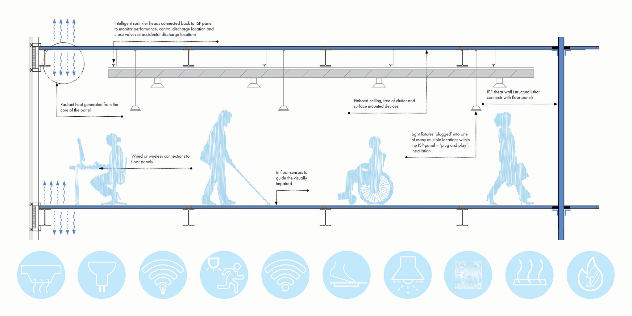
sparkbird's first invention, the Intelligent Structural Panel, started in 2017. It takes all the components and processes that go into constructing a floor and shear wall in a building and combines it into one product, including the mechanical, electrical, and IT. Microsoft saw an early mockup, invited WZMH into their IoT (Internet of Things) and AI Insiders Lab, and accepted them as the only architectural firm in the program.
When it comes to mass timber, four projects are live in the lab right now (and probably more by the time this article comes out - they move fast).
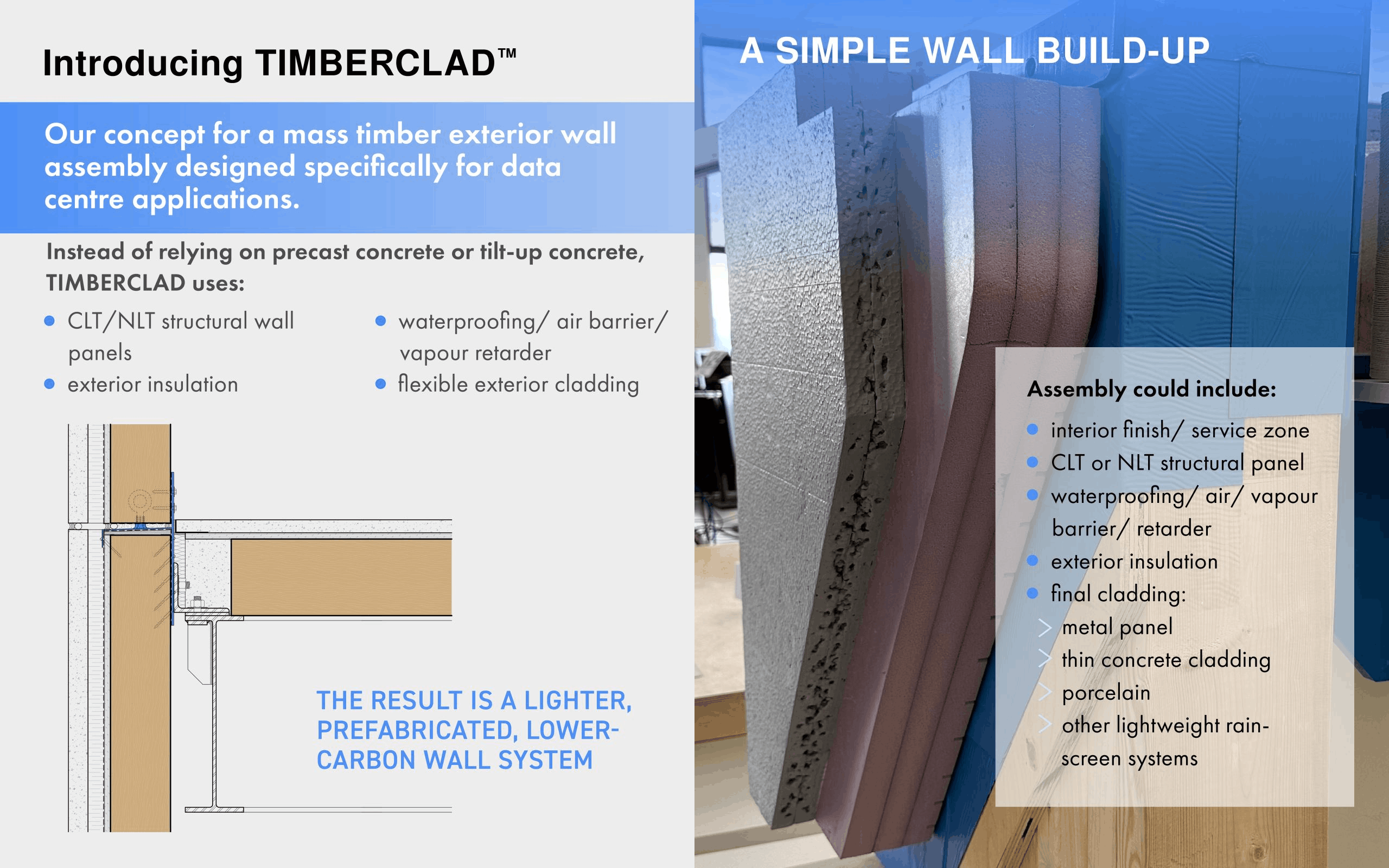
TIMBERCLAD™ is a mass timber exterior wall system aimed at data center construction. CLT or NLT panels paired with exterior insulation, air and water barriers, and flexible cladding options, designed to replace precast or tilt-up concrete walls. Lighter, prefabricated, lower-carbon. WZMH has a full-scale mockup of it in their office and is testing whether GripMetal between timber layers can improve composite action and stiffness under wind loading.
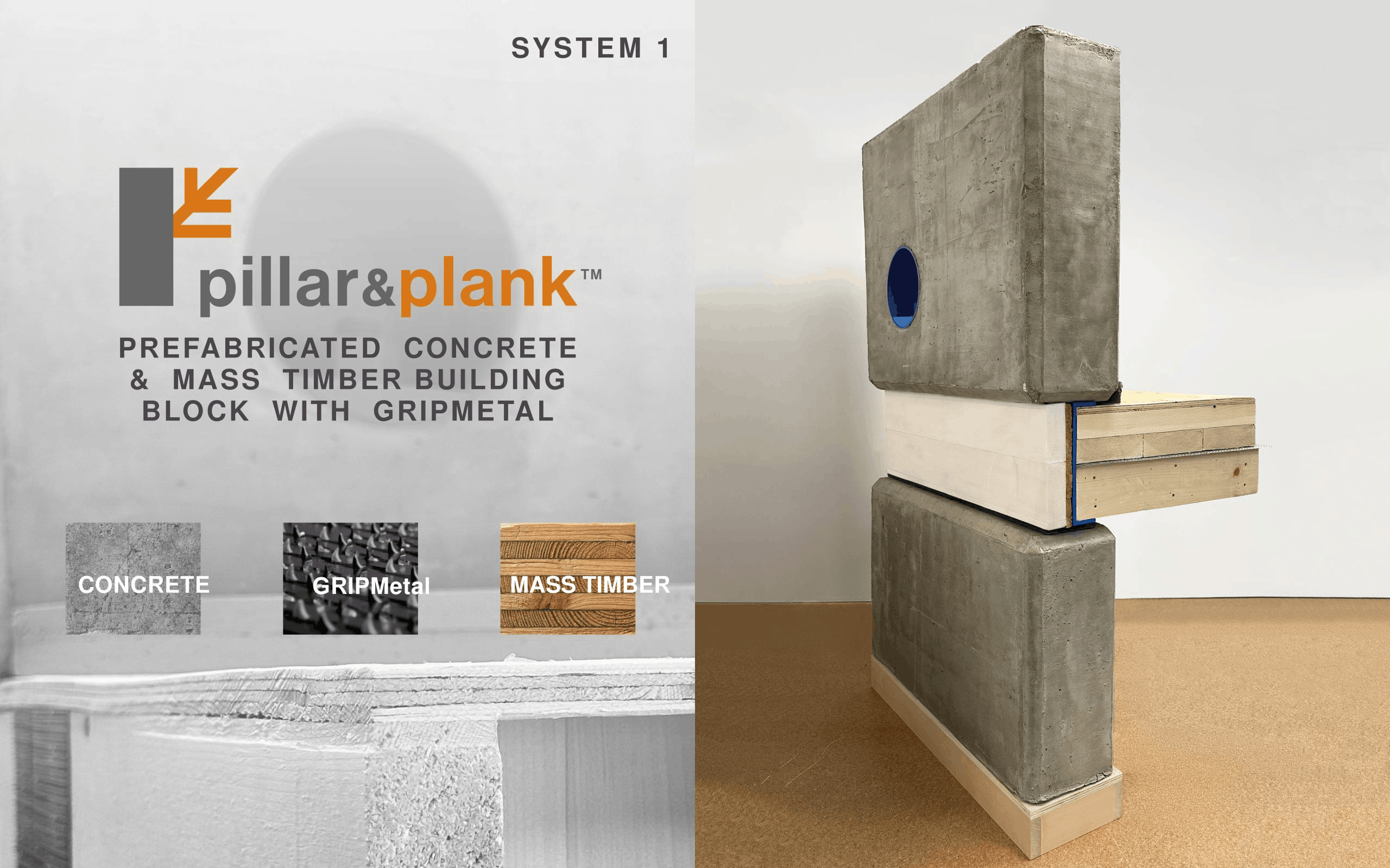
Pillar & Plank is a hybrid system aimed at multi-family residential, where clients want mass timber but are getting hit by cost and lead time. The structure combines precast concrete piers with mass timber floor panels, with or without GRIPMetal reinforcement. Precast plants exist across Canada, which helps with supply chain and price certainty. The pitch is the same as most good hybrid systems: use each material where it makes the most sense, rather than forcing one material to carry the whole building.
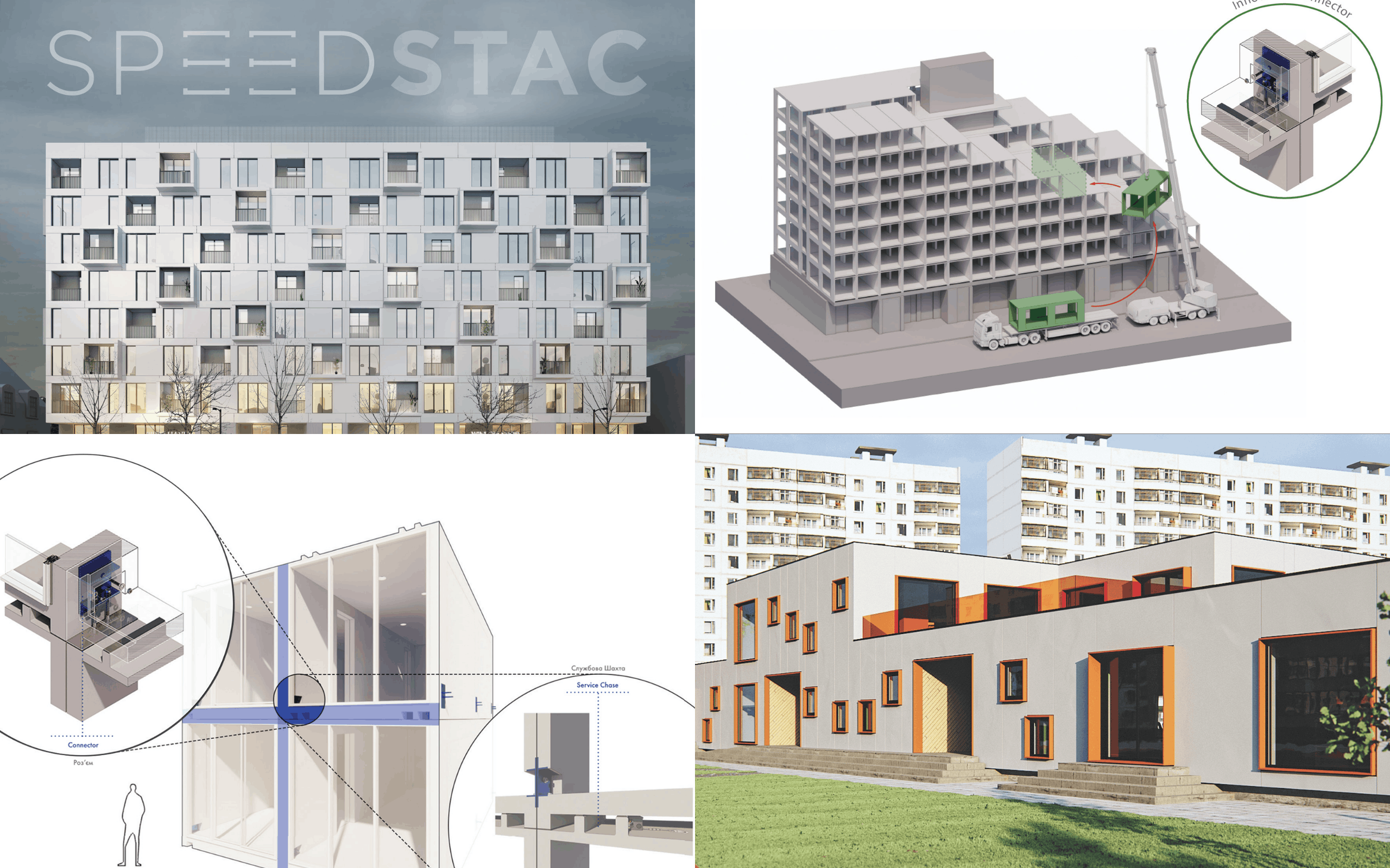
Speedstac is a modular building block system with built-in electrical and plumbing, designed to slide into damaged buildings by crane and replace destroyed sections without demolishing the whole structure. It started as a North American housing solution and pivoted to Ukraine after the 2022 invasion. The dimensions of Soviet-era apartment blocks turned out to match Speedstac modules almost exactly. WZMH won the Architect's Award at the 2023 Rebuild Ukraine competition, sponsored alongside Autodesk and Kingspan, designing 200 residential units for Kharkiv's north Saltivka district. A Speedstac kindergarten concept goes up in 10 working days. The system has both concrete and mass timber versions.
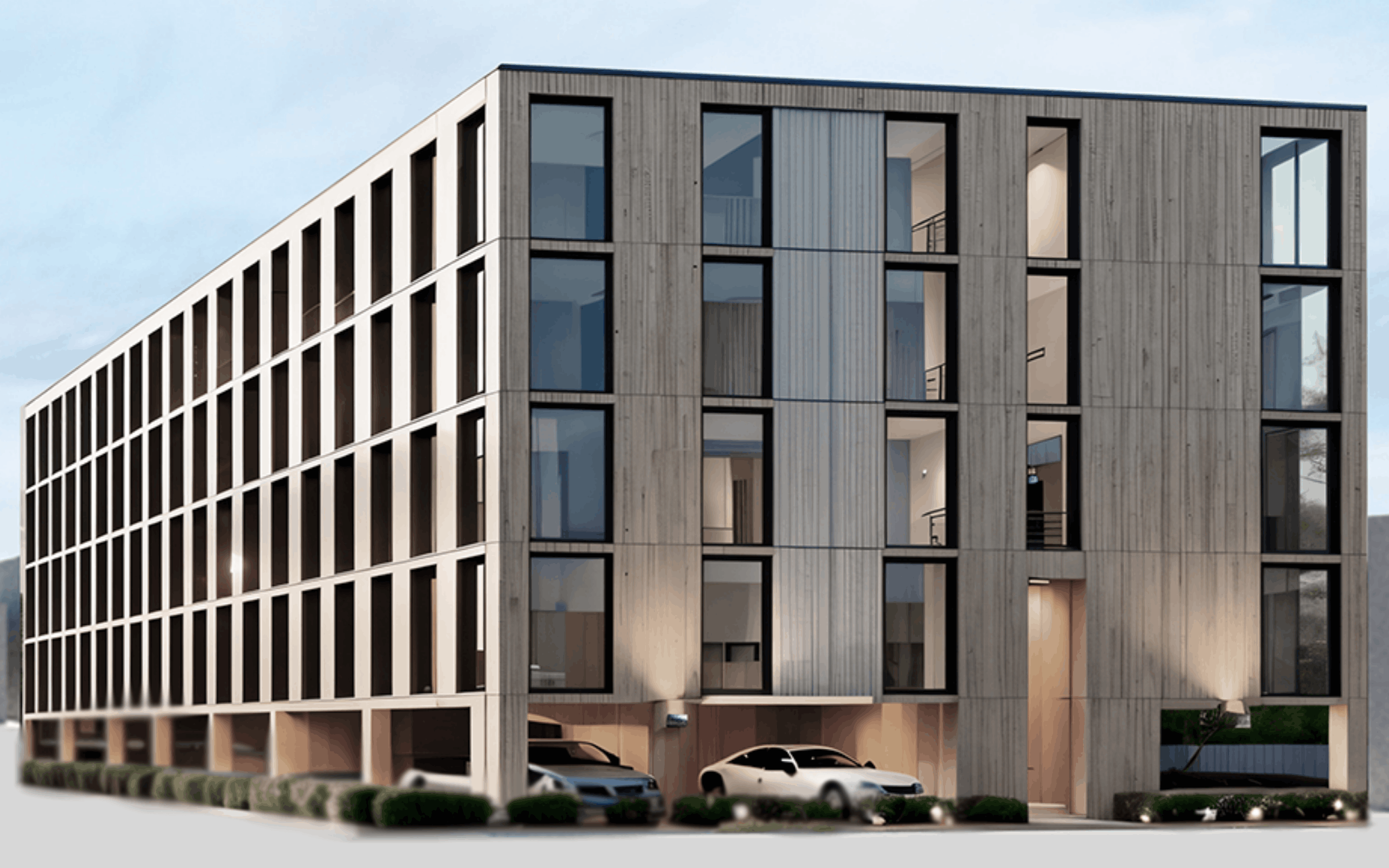
ELEVATE is the housing model. Build rental apartments on stilts over under-used community sites, decentralize the mechanical room into in-suite utility closets, and structure the deal so the host institution gets a revenue stream instead of selling land.
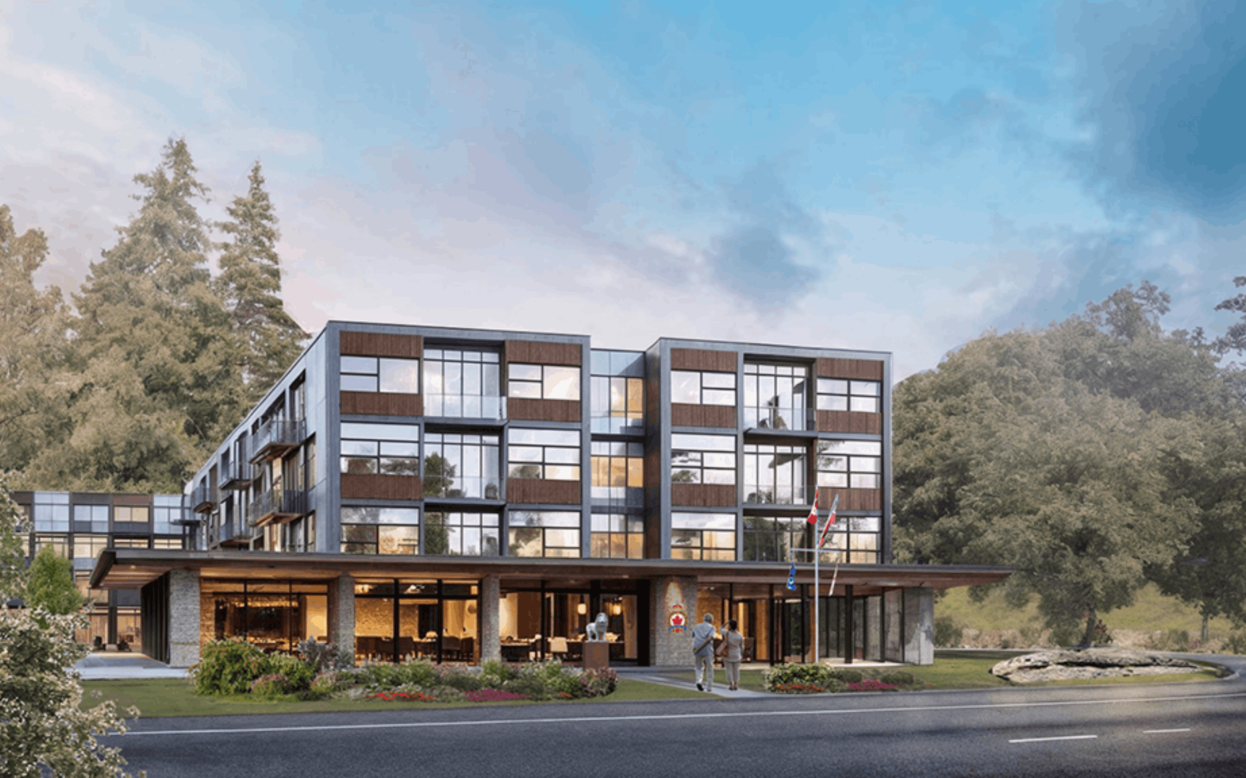
The first live project is in Bala, Ontario, where WZMH is replacing a 1970s Royal Canadian Legion hall with a larger legion facility on the ground floor and apartments above. The legion's signature semi-circle red brick bar will be dismantled and reinstalled in the new building. Demolition is targeted for May 2026. The same platform has been proposed for Toronto library sites.
None of those came from a strategic plan. They came from a team that was given permission to follow what looked interesting. The output is what happens when you keep that permission slip valid for a few years.
If a lab is just a permission slip, the question becomes: what does giving that permission actually do for the firm?
What Running a Lab Actually Does for the Firm
The easy answer is that the lab produces ideas, and some of those ideas turn into products. That's true, but it's the smallest part of what sparkbird has done for WZMH.
The bigger benefits show up in the day-to-day business.
The first is talent. People want to work somewhere that's doing exciting things. In a market where every firm is fighting for the same hires, it’s a real recruiting advantage. New staff gravitate towards the opportunity to invent and explore alongside their more traditional architectural work.

The second is competitive positioning. When WZMH competes for a project against other firms, they’re all showing up with similar portfolios, similar past projects, and similar people. Nobody's resume is really winning the interview. Zenon says sparkbird is what differentiates them.
“We could spend business development dollars on taking clients golfing and for dinners. Or we could spend that money in the lab here. Honestly, the results we're getting for spending the money in the lab are way better.”
The lab is the signal that the firm thinks differently, which is what clients hire firms for in the first place. The lab doesn't even have to be working on the client's specific project. The fact that the firm is the kind of firm that runs one says enough.
The third benefit is the longest to materialize and the hardest to measure. It's a different way of thinking. Teams that have spent time prototyping in the lab bring a different mindset back to their day-to-day work. They're more willing to question why something gets detailed a certain way, more comfortable proposing an unfamiliar assembly, more curious about what's actually possible.
The bet isn't on any single product. The bet is on what the lab does for the firm over time. Talent, positioning, mindset, and occasionally a real product that changes how something gets built.
If a lab does all that for one firm, the obvious question is what the industry would look like if a lot more firms ran one.
What If More Firms Did This?
Construction is one of the only major industries that hasn't fundamentally changed in a hundred years. Manufacturing has. Healthcare has. Aerospace has. The list of industries that have made big productivity leaps in the last fifty years is long. Construction isn’t on it.
There's no shortage of explanation for that. Fragmented supply chains, slow code cycles, project-based risk, conservative clients, thin margins. All real. But there's also an explanation that doesn't get said out loud often enough: most of the people designing buildings don't see inventing the parts - as part of their job.
Manufacturers are running businesses that depend on selling things they've already figured out how to make. The economic incentive for radical change sits with whoever is willing to spend time and money on something that might not work. And historically, that's been a small number of researchers in universities, an even smaller number of firms with their own labs, or the occasional tinkerer trying to make something better.
If a hundred more firms ran labs, even modest ones, that changes. Hundreds more people experimenting with hybrid assemblies, alternative materials, new connections, smarter mechanical layouts. Most of those experiments wouldn't go anywhere. But a few would.
A network of firms running labs, sharing what works, handing things off to producers who can ship them, moves things a lot. Mass timber in particular is the kind of category that would benefit from this. The product set is still relatively small. The supply chain is still developing. The cost curve is still figuring itself out. Every additional firm pushing on what mass timber can do, structurally and economically, accelerates how fast it becomes a default option instead of an alternative one.
The choice in front of most firms isn't whether to build a sparkbird or not. It's whether to keep treating innovation as something that happens somewhere else. The ones who’ve embraced the inventor mentality are already shaping what mass timber gets to be next.
If you're exploring mass timber for your own projects, one of the first questions is often: who actually makes the materials?
To help with that, we created a Mass Timber Producer Map featuring 39 North American producers and fabricators. You can explore manufacturers near your project, see the products they produce, visit their websites, and connect directly with them.
👉 Get access to the Mass Timber Producer Map by joining our newsletter!
Getting the Full Mass Timber Look Without the Price w/ Mike Lipke of Torzo Surfaces
Hybrid mass timber is often the smarter structural choice. But it comes with a trade-off most teams just accept. The exposed steel beam. The run of ductwork overhead. A finished building that doesn't quite look like the one in the renderings. You wanted all wood. You got wood plus everything you had to leave showing.
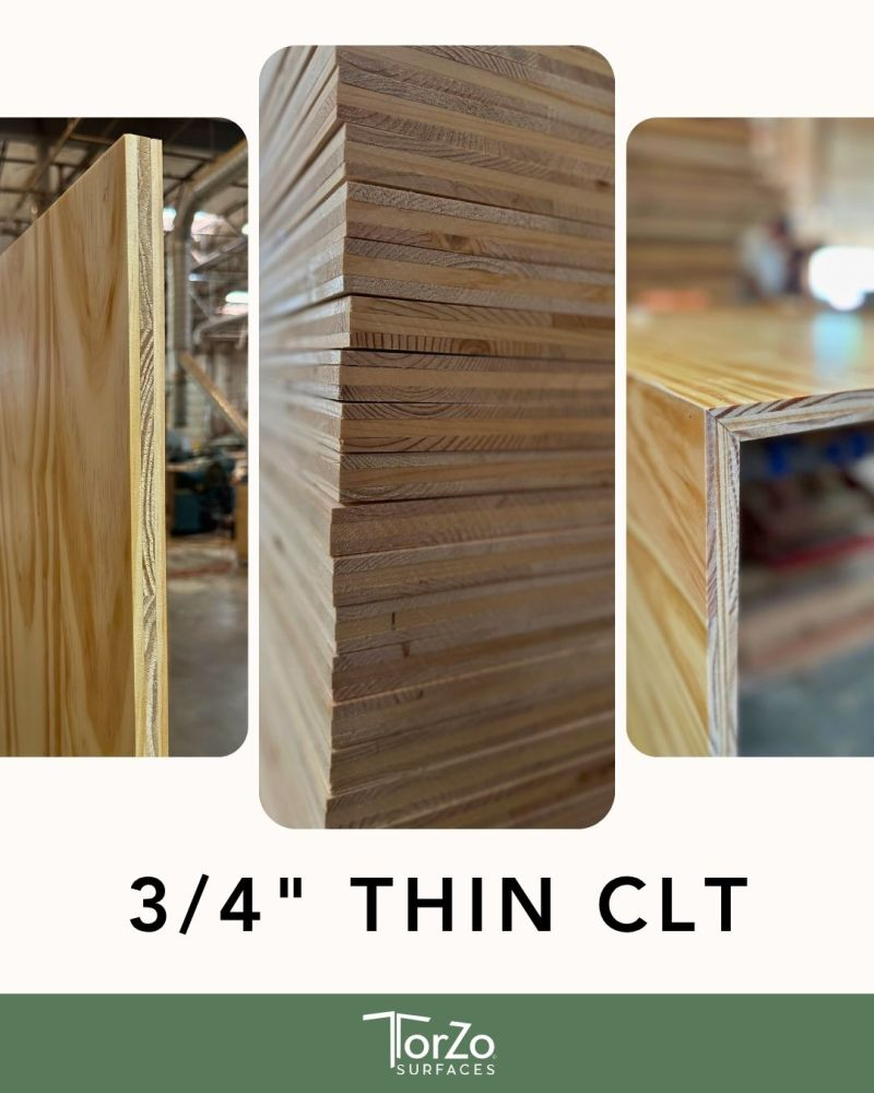
Mike Lipke has spent over a decade making sure you don't have to accept that. He's the president and owner of TorZo Surfaces, the only U.S. manufacturer of Thin CLT panels. Thin sheets of cross laminated timber, available in almost any species, made from new material or remanufactured scrap. He's been making them since 2011, well before most people in the U.S. had heard of CLT.
In this piece Mike breaks down what Thin CLT actually is, the problems it solves on a jobsite, how it gets made from both new wood and salvaged material, and what the demand for it says about where mass timber is headed.
This article is just one part of the newsletter where we cover who and what’s shaping the mass timber industry.
👉 Stay ahead of the mass timber industry & grow your network. Join Our Newsletter
What Thin CLT Is and What It Solves
Thin CLT is a 4x8’ cross laminated timber panel ¾” thick (standard, they can make custom sizes too). It's designed that way to be familiar with crews used to working in standard plywood and OSB dimensions.
Most of the time, the job is cladding. In a mass timber building, that usually means covering up something that isn't wood. A steel beam. Concrete. Mechanical and HVAC ducting. You wrap it in a panel so it looks like mass timber. Most commonly, Mike sees it used as a beam wrap.
A lot of mass timber buildings put a steel beam in here and there, and the team wants it gone. Covered. Looking like the rest of the wood. Normally, that means using a different wood product (and mismatched look), or a full-sized mass timber piece that comes with a bigger price tag. But, with Thin CLT, you don't need the full-sized panel to maintain the consistent aesthetic.
On a big field nobody sees the edge of a panel in the middle of that wall, nor is it carrying any sizable load. There's no reason to pay for the structurally sized members there.
Instead, Mike laminates the exact same species, grade and finished material onto a cheaper backer, getting the exact same look, and saving the money. The whole wall looks like the same CLT construction as the main structure, even when most of it isn't.
How It's Made: New Wood and Salvaged Scrap
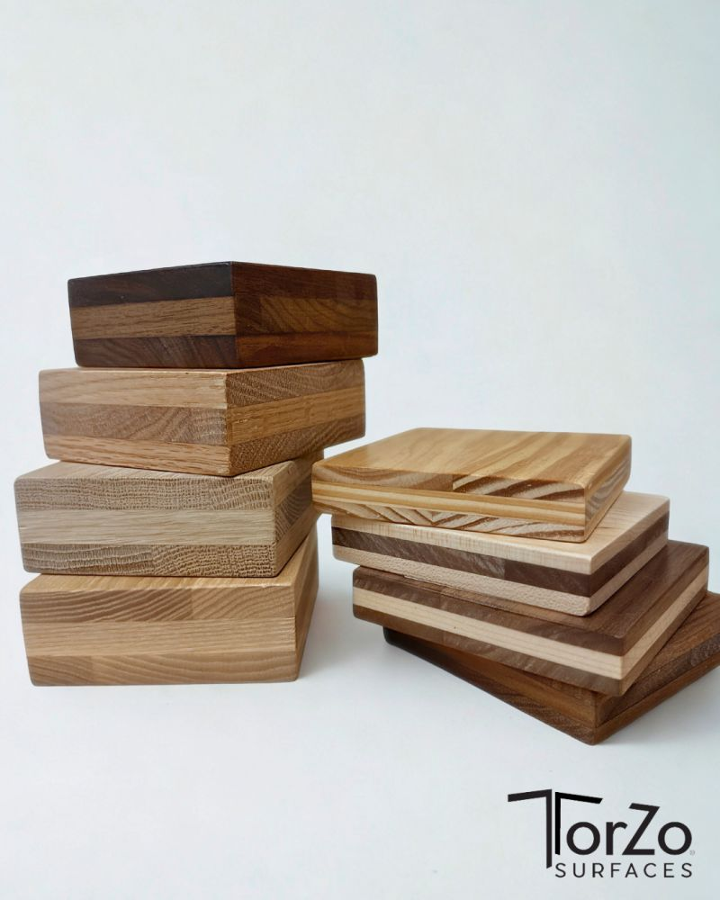
The new-wood process starts with standard dimension lumber. Two by fours, two by sixes, any species. Torzo re-saws it into thin layers, glues the strips into sheets, then laminates the sheets together in a normal 3-layer CLT pattern to make the panel.
You might be thinking, why not just use a single layer of the face material? In a perfect world, or with a perfect material, that would work. The problem is that wood isn’t perfect.
It moves. It drys. Bends. Warps. And twists. And then, no 2 pieces are alike. They do all that in different ways, times, and cycles. Using just the face material in a single layer would give you a very unstable material. Using multiple layers and putting the more “spirited” pieces in the middle stabilizes and distributes all that action across the panel and keeps it stable.
So when you want a “clear” panel look (no knots, checks, decolorization) you can get a perfectly clear face while the knottier material goes inside (the middle) where nobody sees it. The face (and/or the back) match what the customer wants. And nothing gets wasted.
.png)
Mass Timber in the Data Center Boom w/ Erik Barth of Gensler
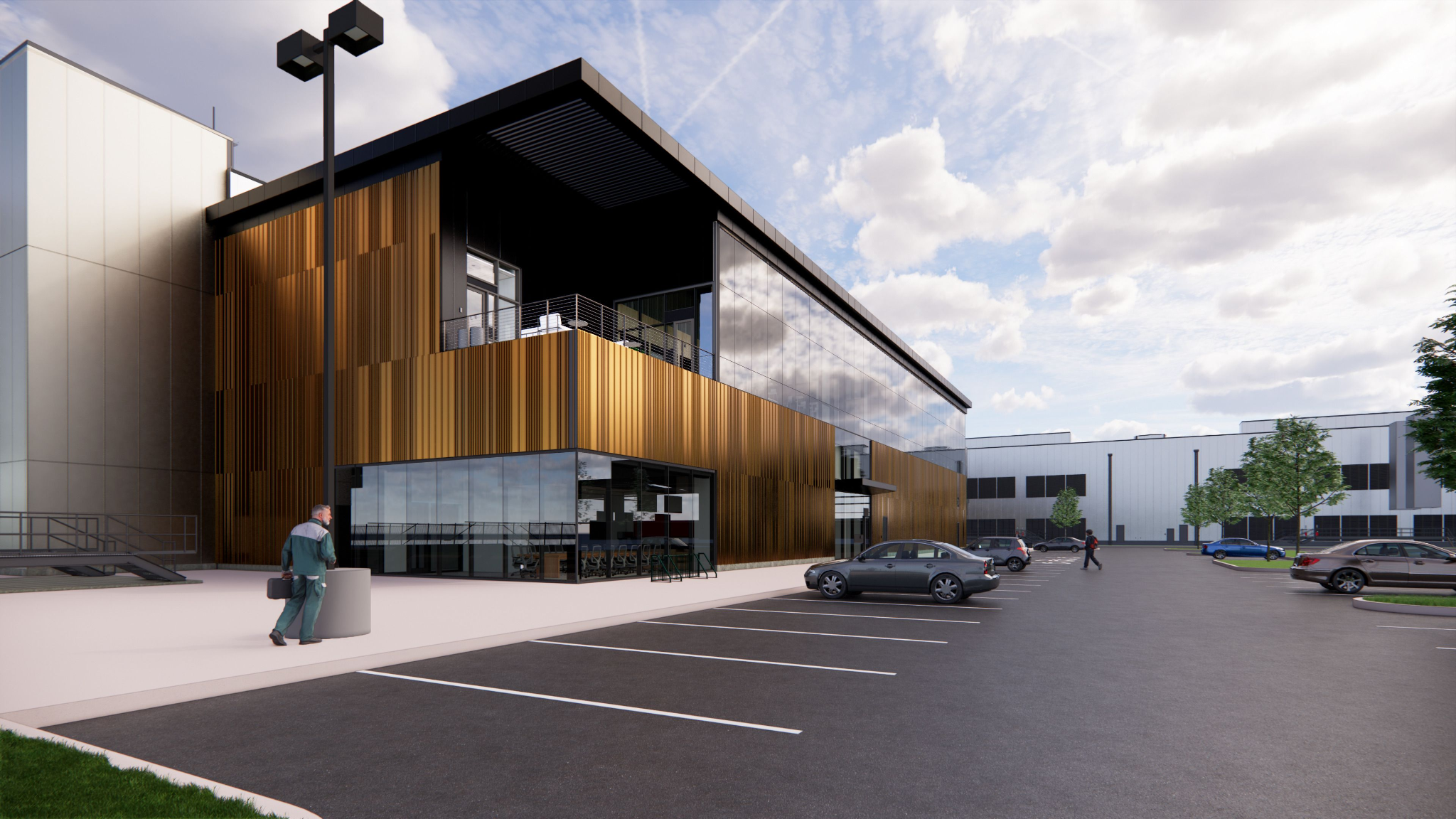
Office buildings in major U.S. metros are sitting at roughly 20% vacancy. Data centers? Less than 1%. Right now, the U.S. is building data centers at a pace the construction industry has never seen, and no other commercial real estate category is close.
For the mass timber world, that's a real opportunity. The carbon math is there. Mass timber runs roughly 35 to 40% less embodied carbon than steel and up to 60 to 70% less than concrete. The buildings themselves run 500,000 to a million-plus square feet apiece. And the speed advantage of prefabricated mass timber lines up with one of the things data center owners need most: a lot of square footage built fast.
Erik Barth, AIA is one of the people figuring out what doing this well actually looks like. He's a Senior Associate at Gensler in Boston and leads the firm's Mass Timber Collaborative, a team that's been working on mass timber projects for roughly seven years. In this piece, Erik walks through where mass timber fits in the data center boom, why Type III construction has become the sweet spot, and how to design a building today that doesn't end up half-empty in 2040 for the same reasons a lot of office towers are now.
👉 Stay ahead of the mass timber industry & grow your network. Join Our Newsletter
Where Mass Timber Fits in the Data Center Boom
The demand picture for data centers is unlike anything else in commercial real estate. Computing power keeps growing, and that power needs a physical home. Storage and processing have to live somewhere, and they have to be close enough to power infrastructure and fiber to actually work.
That's why data center location is so constrained. Three factors have to overlap: serious power infrastructure, access to fiber cable, and affordable land. Where all three line up, you get a viable site. Most of the time that's outside major urban cores, which is why data center clusters form in specific regions rather than spreading evenly across the country.
Most of these buildings are one story, sometimes two.
Can the Structure Handle It?
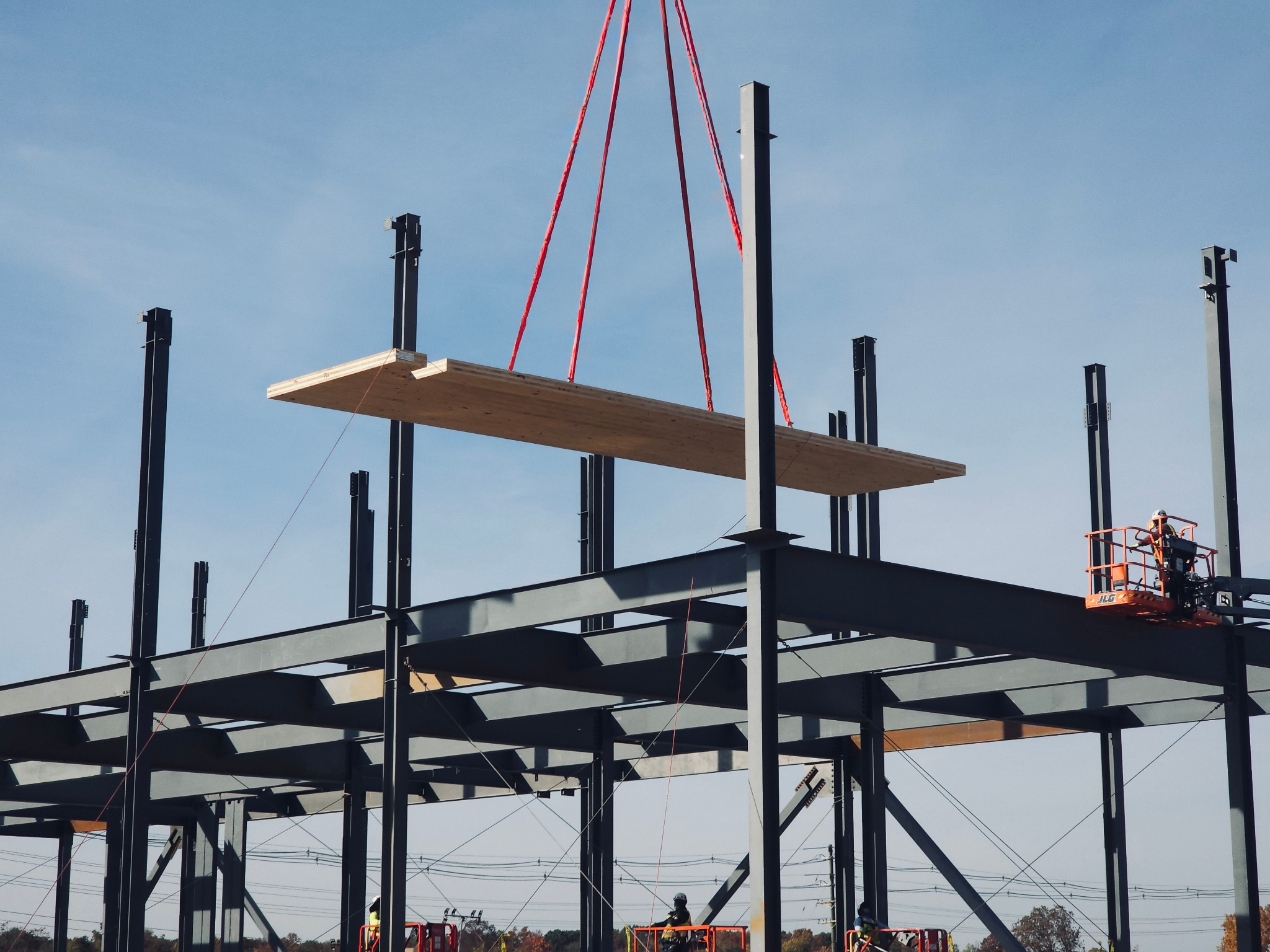
One question that comes up with mass timber and data centers is whether the structure can handle the weight of high-density equipment. Erik's experience is that GPU and CPU loads are the defining structural driver, not the cooling system. His team solved for that with a five-ply CLT panel on a steel primary system, with a topping slab. That assembly handled the load comfortably for the projects they've worked on.
A single-story building is structurally simpler. You're basically putting a roof on a slab-on-grade. Two stories adds efficiency by stacking colos (colocations, the server rack groupings) but raises the structural complexity. Either configuration works for mass timber, depending on the site and the program.
The pitch for mass timber inside that program comes down to two things. First, the sustainability and biophilia story is real. Lower embodied carbon than steel or concrete, a positive economic impact for rural forestry communities, and a natural material that the operations staff inside the building actually get to be around. People don't always think about data center occupants because the buildings exist to house equipment. But these facilities need staff to monitor that equipment around the clock. You don't turn a data center off. The people working in them benefit from being around wood, especially over long shifts.
Second is speed. Mass timber gets prefabricated off-site and assembled on-site with smaller crews and shorter timelines than steel or concrete. For a building type that has to come online fast, that's a structural advantage in two senses of the word. The construction itself is also faster, lighter, and quieter, which makes mass timber a better neighbor in the communities where these buildings go up.
The case for mass timber in data centers is clear. The harder question is how to actually permit one.
The Code Path: Why Type III, Not Type IV
Code is where data centers get complicated. The scale alone is a challenge. You're talking about 500,000 to a million-plus square feet under one roof, with massive air handling, heavy equipment, and high power loads. Historically, data centers have been built as Type II construction.
When Erik's team started looking at mass timber for data centers, the obvious first instinct might have been the new Type IV subtypes that were written specifically for mass timber. In practice, Type IV created more problems than it solved.
The reason is air cooling. Most data centers running today use air-cooled systems, which require open plenum space for return air. Type IV doesn't allow a concealed plenum without fireproofing, which eliminates much of the efficiency that makes mass timber worth specifying in the first place. So Type IV and air-cooled data centers don't play well together.
Type III turned out to be the sweet spot. The primary structure doesn't need to be fire rated, which creates efficiency for connections, member sizing, and overall cost. The plenum space stays open. And the team was able to get the necessary square footage through a code variance.
Staying Ahead of a Moving Target
Data center technology is changing fast, and code is changing with it. Air cooling is the norm today, but liquid cooling is coming. Battery storage layouts are evolving, with some buildings centralizing battery rooms and others distributing them across the facility. Every one of those shifts has code implications for ratings, separations, and structural approach.
Erik's advice: stay involved in the discussions happening at the International Code Council (ICC). Don't get caught off-guard by updates. A static code strategy isn't going to hold up across a technology cycle this short.
The code path gets the building built. The next question is whether it still works ten years from now.
Designing for What Comes Next
There's a popular intuition that data centers are a temporary problem. The thinking goes: equipment keeps getting more efficient, so the buildings should eventually shrink or disappear. Moore's Law and all that.
Erik isn't seeing that on the ground. Yes, individual chips are getting more efficient per unit of volume. But the demand for both storage and processing keeps outrunning the efficiency gains, especially with AI. The support equipment around the racks isn't shrinking. So even as the technology itself gets better, the buildings aren't going away. They're just packing more capability into the same footprint.
That changes what future-proofing looks like. The primary job is designing the building to keep working as a data center as the equipment inside it evolves. Beyond that, there's a secondary benefit: a well-designed mass timber shell gives you optionality you don't get with other materials.
Mass timber helps with that in two ways. The first is end-of-life. Mass timber can be disassembled in ways that steel and concrete can't, which means materials can be reused if the building eventually does come down. The second is the building shell itself. A large structural grid and tall ceilings give you a clean, open shelf. Even within the strong design constraints of a data center program, that shell can support a wide range of future uses if the technology eventually shifts to something the building wasn't originally designed for.
Designing for the unknown takes discipline. The other half of getting this right is committing to mass timber from the start.
Commit Early or Don’t Commit
Erik's advice for owners and developers considering a mass timber data center comes back to one thing.
"It's important to commit to it up front. The sooner you can fully commit to a mass timber building and not look back, the more successful it's going to be and the more you'll be able to realize the efficiency that's inherent to the material."
Parallel costing and structural comparisons have their place. But the projects Erik has seen succeed have a team that picked the material, locked it in, and stopped re-evaluating it. The efficiency mass timber offers, in speed, in carbon, in build quality, only shows up when the team designs around the material from day one.
The early data center projects being built in mass timber today are proving the structural and operational case. The next phase is normalizing it. As more of these buildings come online, the precedent gets stronger, and the question shifts from “can mass timber work for a data center” to “why wouldn’t you build one this way.”
If you're exploring mass timber for your own projects, one of the first questions is often: who actually makes the materials?
To help with that, we created a Mass Timber Producer Map featuring 39 North American producers and fabricators. You can explore manufacturers near your project, see the products they produce, visit their websites, and connect directly with them.
👉 Get access to the Mass Timber Producer Map by joining our newsletter!

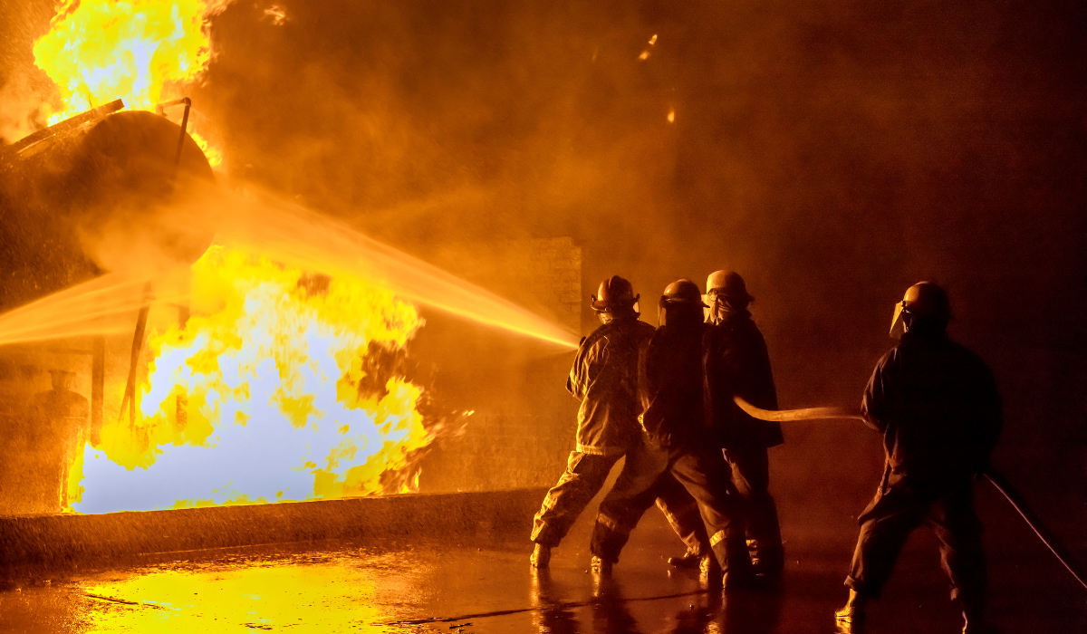
The Fire Department Mass Timber Strategy w/ Erich Roden and Mason Brandt
Most project teams don't know how to have the mass timber conversation with a skeptical fire department. And even when they do, it usually goes wrong, because by the time the meeting happens, it's too late to matter.
Erich Roden, retired Deputy Chief of the Milwaukee Fire Department and founder of Murphy Roden Group, took a meeting with the project team behind the Ascent (world’s tallest mass timber building) and has spent the years since walking other departments through that process.
Mason Brandt, P.E., President and Principal Engineer of WoodCore Engineering joins to bring the designers perspective to the table. He explains where, why and how to put mass timbers together to meet fire code AND give confidence to fire departments.
Between them, they cover where fire service skepticism comes from, what mass timber actually has to do at the connection and member level, what the Ascent project taught everyone involved, and what fire departments in unfamiliar markets need to see before they sign off.
Where the Distrust Comes From

The fire service's caution around wood construction isn't abstract. It traces to specific fires, specific deaths, and specific lessons that got passed across generations of departments. On August 2, 1978, 6 firefighters died at the Waldbaum's Supermarket fire in Sheepshead Bay, Brooklyn, when a bowstring wood truss roof collapsed during a renovation fire. Twelve firefighters fell through the roof when the center section gave way; 6 made it out. A decade later, on July 1, 1988, 5 firefighters died at the Hackensack Ford fire in New Jersey when another bowstring truss roof collapsed. The adage that grew out of those fires, "don't trust the truss," is still being repeated in the fire service today.
That caution expanded as the residential industry shifted in the 1970s to light frame wood products. Departments started losing firefighters to floors that collapsed faster than expected. The wood industry, in the fire service's view, had a track record. Mass timber arrived carrying that legacy, even though the materials, the engineering, and the testing behind it look nothing like what came before.
Erich points to a parallel that gets missed. Type IV buildings, the post-industrial heavy timber type common in cities like Milwaukee, do not collapse in fires. The standard refrain from firefighters after a five-alarm fire in one of those buildings is some version of "I can't believe what a shellacking that building took, and it's still standing." The dimensional size of the lumber is doing the work. Those stories don't make the textbooks or the peer-reviewed journals, so the lesson never gets institutionalized inside the fire service.
Most firefighters working today inherited the distrust from older generations and are weighing mass timber against the lightweight construction era, not the heavy timber one.
Closing that gap means showing fire departments what mass timber actually does under fire conditions, starting with how the system holds itself together.
How Firefighters Look at Buildings
Mason brings up a common misconception. Concrete and steel don't burn, but that's not the same as "concrete and steel buildings don't fail in fires."
The three primary structural materials behave differently in a fire. Steel loses strength as it heats, elongating at high temperatures, which pushes outward on connections and walls and destabilizes the structure from the inside. Concrete spalls when superheated water inside the slab boils, exposing the rebar, which then heats and elongates the same way. Wood does neither. It loses section at a predictable rate (roughly 1 inch per hour), doesn't push walls outward, and starts extinguishing itself once the apartment contents are out.
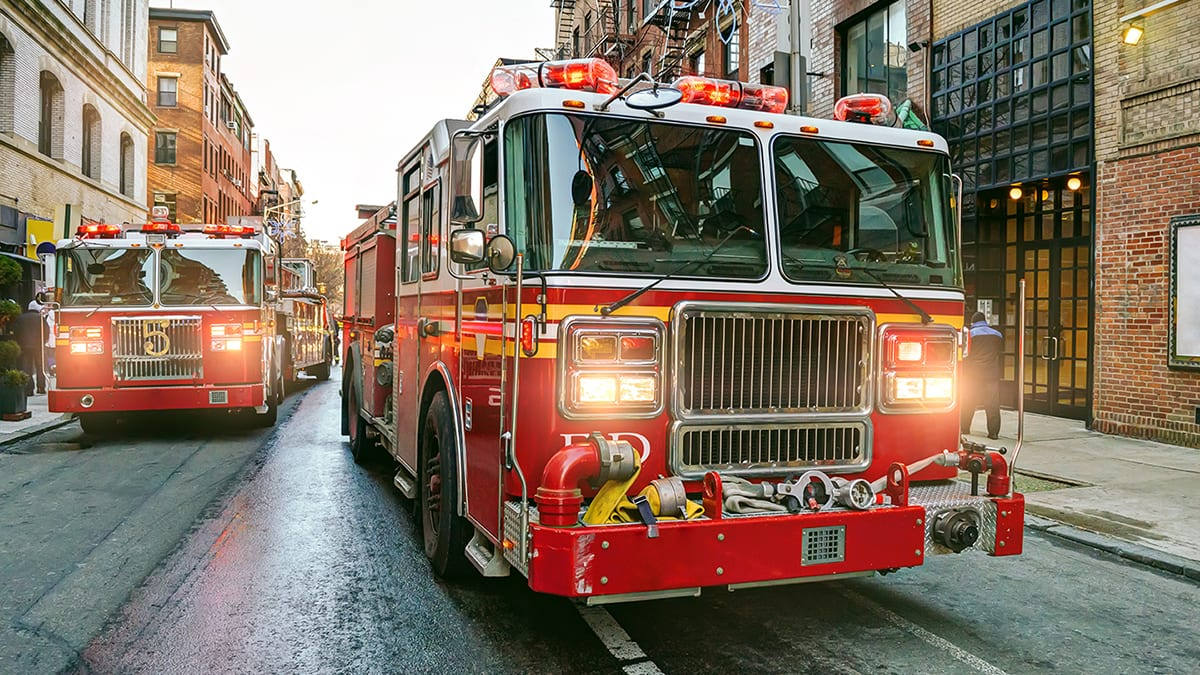
What gives a fire department confidence to keep crews inside a mass timber structure comes down to a few things. Concrete stairwells give fire service teams confidence because it’s the beachhead they launch operations from. Sprinkler systems doing the lion's share of the work before crews even arrive. Connections without exposed steel, where openings and gaps in steel hardware are sealed up and protected from direct fire attack. And firefighting tactics that don't have to change.
When a fire department arrives at a fire, they don't think in material categories. They think in failure modes. What’s the building going to do as the fire burns? Where can my crew safely operate? What’s the sequence I'm watching for that tells me to pull out?
That’s the lens a fire department evaluates a structure through. It’s also the lens designers need to design through if they want a fire department's confidence.
For designers, the takeaway runs through every detail. Build for predictability. Detail connections that behave the way the rating says they will. Don't put exposed steel where it becomes the failure point. Provide cast-in-place stairwells where firefighters need them. The fire department's job is to understand the building as it burns. The design team's job is to make the building easy to read.
The performance is one thing. The Ascent project showed what it takes to get a fire department comfortable enough to approve it.
The Ascent Strategy
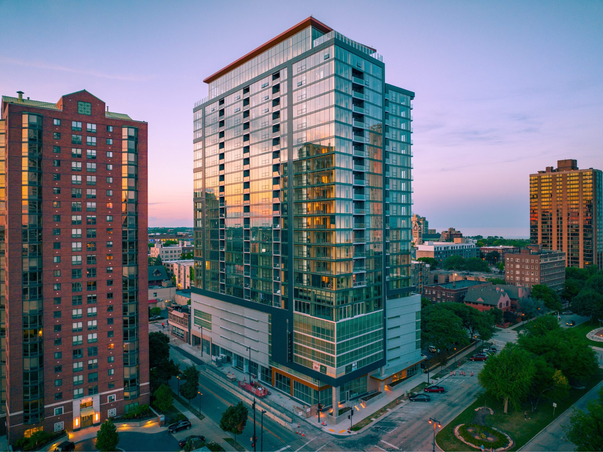
Erich calls it a Cinderella story. He was a battalion chief at the time. The fire chief's secretary asked him to come downtown. A local developer, New Land Enterprises, was proposing a 23-story wood building on one of Milwaukee's busiest avenues. The chief had questions and wanted Erich to handle them.
The first surprise came at the initial project meeting in the fall of 2018. The room had New Land, the architect (Jason Korb of Korb Architects), the structural engineering team (Thornton Tomasetti), and the rest of the design and approvals teams. The fire department had been pulled in, but not to sign off on a finished package. Partway through the meeting, Erich realized the building wasn't permitted yet. The team wasn't there to walk the fire department through a project that was already approved. They were there to hear the fire department's concerns before they got started.
That was the opposite of how those meetings normally go. The standard pattern is the fire department comes in at the end. New Land Enterprises flipped that. They wanted to know what the fire department was worried about, what they wanted to see during construction, and what they wanted in the final building. Erich raised the structure-during-construction concerns: sealing the building four floors below the active level, no debris, no smoking or grilling on site. New Land Enterprises agreed to all of it.
The second surprise was the testing. The developer needed variances to exceed the 2015 IBC, which Milwaukee was operating under at the time. The Ascent's design exceeded the code by a wide margin, so performance-based testing was the path. The Forest Products Lab in Madison ran the test. The team put one of the mass timber slated for the project into a furnace and ran it at 3,000°F for three hours. When they pulled it out and chipped away the char layer, the timber retained its structural integrity. Erich watched through the sight glass.
The trade New Land Enterprises offered to get the variance package signed was straightforward. Gypcrete in the public hallways, which firefighters use as a beachhead during operations. In return, two more stories. The building landed at 25.
The third surprise was construction. The Developer and the contractor (C.D. Smith) offered the fire department unlimited site visits. By the time the project finished, most of the firefighters in the city's 36 firehouses had been through it.
The result Erich points back to most often isn't the building itself. It's the conversion. The standard line from his crews after a tour was some version of "Hey chief, you know how much fire it would take to burn this amount of wood down?"
That sound bite, repeated across firehouses, did more for the fire service's view of mass timber in Milwaukee than any peer-reviewed paper could have.
What worked at Ascent is starting to translate to other markets, but the conversation looks different in cities that don't have a project like the Ascent yet.
Going East
Mason and his team are seeing roughly two to three times the project pipeline on the East Coast as on the West Coast. States with deep timber histories like Maine, New York, New Hampshire, Pennsylvania, and Virginia are showing serious project interest, along with Michigan, Wisconsin, and Minnesota in the Great Lakes region.
The fire service in those markets is moving too. Erich points to FDNY as the bellwether. A few years ago, when he gave a lecture with the head of buildings for New York City, the fire department's posture was a flat no. Not in my backyard. The concern wasn't ignorance about the material though. It was the institutional risk of being the official who signed off on a tall mass timber building in midtown Manhattan or downtown Brooklyn. The answer was no.
That’s changed. The most recent issue of WNYF, the FDNY's trade magazine, ran a mass timber piece that walks through what the buildings are, where the code is heading, and why the city is now involved in the research and code-writing for it. Erich's view is that as FDNY goes, the rest of the fire service follows. With the largest fire service in the country putting eyes on mass timber and engaging with the industry, the institutional posture downstream of that decision tends to follow.
For developers and design teams entering markets where the local fire department hasn't seen a mass timber project before, the strategy is pretty straightforward.
Bring the fire department in early, in the concept phase. Share the test data. Tell them which municipalities have approved similar buildings and offer to put them in touch. Walk through the firefighting operations and confirm that nothing about how their crews fight a fire in a tall mass timber high-rise is different from how they fight one in a Type IA building. And invite the fire department onto the site during construction so their members get more comfortable with the system and products.
Mason adds the practical framing for why early engagement matters from a project standpoint. A developer who builds and flips moves on. The architect and engineer move on. The fire department is left with whatever has been built for the next 30 to 50 years. When fire departments get pulled in at the end, the relationship is adversarial by default. The dollars are committed and the design done. Bringing them in at concept gives them a chance to alleviate concerns before the project is shaped, which gets them to a productive role on the team rather than a defensive one.
The whole approach hinges on a single line Erich keeps coming back to.
What Fire Departments Need
The fire service's job isn't to stand in the way of economic development. It's to make sure the codes are enforced, the buildings are understood, and the firefighters who'll respond to the next call have what they need to do their work safely. Mass timber clears that bar. The buildings that have been built, the testing that's been run, and the projects like Ascent that pulled the fire department in early are the proof.
The instructions for any developer or design team stepping into a new market are short. Bring the fire department in early. Show them the data. Walk them through the building. Ask what they want to see. Let them ask their questions. The conversation goes faster than most people expect.
Erich's framing for the whole thing is one line.
"We're not gatekeepers. We can be convinced that these buildings are safe. Just show us and we'll understand."